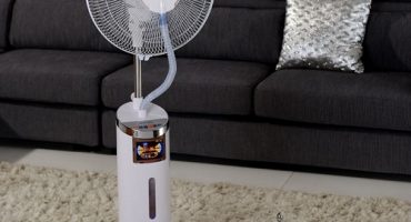
The fan is present in many types of household appliances. In particular, in the bathroom or toilet it is needed to quickly remove moist air through the hood. Natural ventilation in old houses most often does not work intensively enough, because it was developed taking into account the installation of wooden windows (modern double-glazed windows do not allow air to pass through). To establish ventilation in the apartment, exhaust fans are installed. And in order for this device to last a long time, a special regulator has been invented that can reduce or increase the speed of rotation of the plates.
Types and features of the device
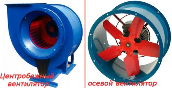
By type of design, 2 types of fan are distinguished:
- Axial. There is an engine with an external rotor. An impeller is attached to it. The movement of air masses coincides with the axis of the rotor. This type of fan has the advantage of being compact. His productivity is average. Suitable for small and medium rooms. That is, the place of installation of the fan should not be further than 2 meters from the ventilation outlet.
- Radial (centrifugal). Here the plates are attached to a special ring. Air enters the device from the front side, and exits from the side at a right angle. Unlike axial, a radial fan is more efficient. It is mounted in large rooms with an area of more than 12 cubic meters.
Types of exhaust fans
For the bathroom, they mainly choose an axial view, because few people can boast of a spacious area in this room. The cost of such devices is small. The fan does its job well if the distance to the ventilation outlet is selected correctly. But if it exceeds the maximum value - 2 meters, then it is worth considering the radial version of the device.
Exhaust fans are also classified by how the design was installed. Installation can be done:
- on the wall;
- to the ceiling;
- both on the wall and on the ceiling (you need to choose where);
- into the ventilation duct.
The channel type characteristic requires special attention. Such devices are mounted in the gap of the ventilation duct. It is used when there is only one channel, and you need to connect more rooms to it. However, this does not mean that it cannot be purchased even when one room is connected.
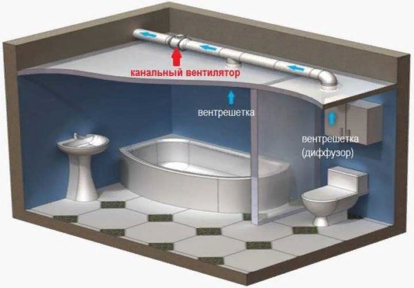
Duct exhaust fan
The choice in the direction of the duct fan is made in rare cases, because the process is longer, and further maintenance (cleaning, replacement) is difficult. This does not apply to private houses, because there it can be laid in the attic, which greatly simplifies the task.
Why adjust the speed
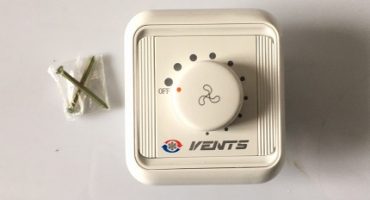
Speed controller (speed controller) - a device whose function is to reduce and increase the number of revolutions of the exhaust fan. This is ensured by a change in voltage that is supplied to the device. To work, it must be connected to the fan according to a special scheme (we will talk about it later).
By the specifics of its device, the fan always works at full power, which significantly affects its service life to a lesser extent - the elements wear out quickly and break down.
Important! Work "at maximum" not only leads to a quick breakdown, but also consumes electricity greatly.
Therefore, it is useful to know how to reduce the speed of the exhaust fan to increase the operational life of the equipment.
In addition to increasing wear resistance, the fan with the controller starts to blow quieter, electricity is consumed to a lesser extent.
The main types of regulators
All controllers can be divided according to the regulation principle:
- Transformer speed controller. Designed for powerful fans. The engine is single or three phase. The speed reduction is smooth and can be carried out on several devices at the same time.
- Electronic speed controller
- Thyristor speed controller. Prevents overheating of the case, works effectively in single-phase equipment.
- Frequency speed controller.
- Triac speed controller. Most common. Able to cover not one but several engines at once. It is very important that the current indicator does not exceed the limit value, most models are silent.
- Frequency speed controller. These models can be used exclusively in the range from 0 to 480 volts. Suitable for 3-phase motors with power not exceeding 75,000 watts.
Features of the use of devices
First you need to understand the general principle of work. It is aimed at changing the power of the air flow and affects air exchange in general. Speed control is achieved in one of the following ways:
- a change in the voltage supplied to the winding;
- change in current frequency.
In practice, devices of the first type are always used, because a controller based on a change in frequency is sometimes more expensive than the fan itself. Such an acquisition is not further justified by any advantages.
Oddly enough, but the use of controllers is very wide: industrial equipment, public places (restaurants, gyms, office). Everywhere where intensive ventilation and its regulation are needed.
Management can be mechanical and automatic. Mechanical control is carried out using a special wheel, which allows both stepwise and smoothly reduce the speed of the exhaust fan. This control method is typical for triac models.
Controller Connection Rules
We will figure out how to connect the regulator depending on its type.
Let's start with the most common types - triac and thyristor. Their installation is very simple. If there is a necessary scheme, any person will be able to navigate it (see below). Regulation is carried out by the control unit. Each model has its own power - it can not withstand more voltage.
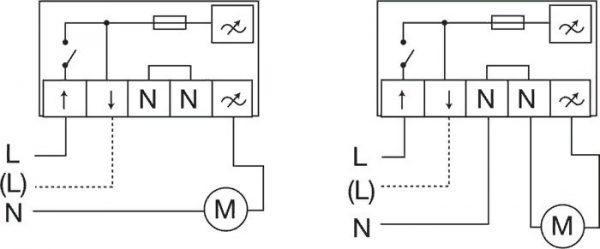
Connection diagram for triac and thyristor controllers
Important! The exhaust fan motor must have overheat protection.
The second type is transformer. The input voltage is 230 volts. The winding has a certain number of branches. To reduce voltage, it is necessary to connect a load to them. After the voltage decreases, energy consumption becomes lower. The switch allows you to connect the motor to the desired area of the winding, and then the voltage changes.
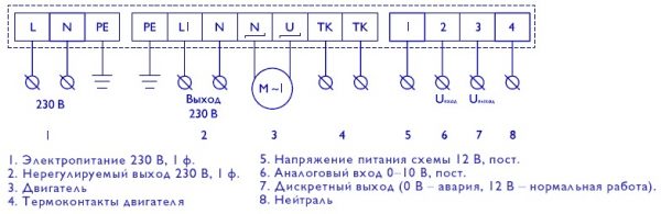
Transformer type connection diagram
If we consider models of the electronic principle of operation, the connection scheme will be different. Here, using pulse modeling, the voltage is changed smoothly. The longer the pulses are and the pause time is shorter, the higher the voltage, and vice versa - short pulses with long pauses indicate a low voltage.
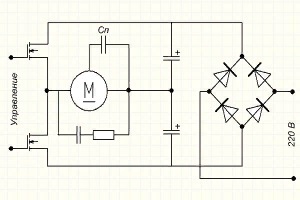
Scheme of models of electronic principle of action
If the fan has a timer, then it works on a different principle - the lighting is turned on with the fan. After turning off the light, the device continues to work for a certain time. Diagram and example of connecting an exhaust fan with a timer in the picture below.
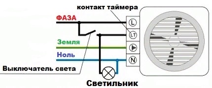
Exhaust fan wiring diagram with timer
A power cable (FZN) is dragged into the junction box, and a two-wire cable is passed from it to the switch.Triple wire to the light source, and 4 wires are connected to the fan. Now you need to make their connection in the supply box.
A blue wire is taken, which is conducted to the lamp, and a blue wire, which goes to the N-contact. They are cleaned and twisted together. Next, you need to take, strip the phase wire, brown from the switch and brown from the exhaust fan (L-contact) and twist these 3 wires together.
Next, we take the yellow supply, yellow from the lamp, yellow from the fan with the ground of the contact - we clean and twist.
Brown from the luminaire, additional from the LT-contact (timer power supply), two-core blue, going to the switch, are twisted together.
The next step is soldering and crimping the wires, insulation and laying them in a box. There are many connection options, but the one described is the most popular and time-tested. The final stage is applying voltage and checking the functionality of the circuit.
Regulator: DIY assembly
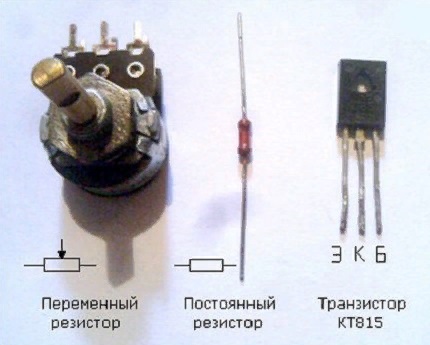
After taking an hour or two of free time, you can build a regulator yourself. You will need:
- resistor (hereinafter - P);
- variable resistor (hereinafter - OL);
- transistor (hereinafter - T).
The base T is soldered to the middle contact of the PR, the collector to the side output. A resistor with a resistance of 1000 Ohms must be connected to the opposite edge of the PR. The second output P is soldered to the emitter T.
Controller assembly
It remains to connect the input voltage wire to T (it is already coupled to the extreme output of the PR). The “+” output is soldered to the PR emitter.
To check how a homemade regulator works, you need a fan. Its positive wire connects to the wire coming from the emitter. The output voltage wire is connected to the power supply.
The negative wire must be connected directly. To check, turn the PR wheel and watch how the number of revolutions changes.
The design is safe (the negative wire is connected directly) - if a short circuit occurs in the controller, nothing will happen to the fan.
The verification process looks something like this:
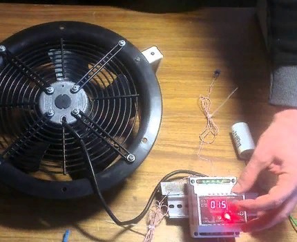
Regulator Check
If desired, you can synchronize the controller with two fans at once, as shown in the diagram:
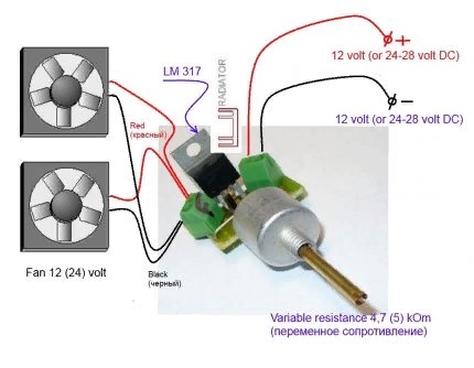
Controller synchronization with two fans
Installation does not take much time, especially if you work according to ready-made schemes. The main thing is to choose the right device for the room. Do not regret the money spent, because clean air is more important. Moreover, you can always save by making the regulator yourself.