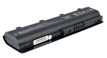
Every motorist had a moment in his life when, by turning the key in the ignition, absolutely nothing happened. The starter did not turn, and as a result, the car did not start. The diagnosis is simple and clear: the battery is completely discharged. But with even the simplest at hand battery charger with an output voltage of 12 V, you can restore the battery within one hour and go about your business. How to make such a device with your own hands is described further in the article.
How to charge the battery correctly
Before you make a charger for the battery yourself, you should find out the basic rules regarding its proper charging. If they are not followed, then the battery life will decrease sharply and you will have to buy a new one, since it is almost impossible to restore the battery.
To establish the correct current, you should know a simple formula: the charge current is equal to the discharge current of the battery over a period of time equal to 10 hours. This means that the battery capacity should be divided by 10. For example, for a battery with a capacity of 90 A / h, it is necessary to set the charge current to 9 amperes. If you put more, then the electrolyte will quickly heat up and lead cells may be damaged. With less current, it will take a very long time to fully charge.
Now you need to deal with stress. For batteries with a potential difference of 12 V, the charge voltage should not exceed 16.2 V. This means that for one bank the voltage should be within 2.7 V.
The most basic rule for the correct battery charge: do not mix up the terminals during connection charger to rechargeable batteries. Incorrectly connected terminals are called polarity reversal, which will lead to immediate boiling of the electrolyte and the final failure of the battery.
Essential Tools and Supplies
You can make a high-quality charger with your own hands only if there are cooked tools and supplies under these same hands.
The list of tools and supplies:
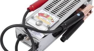
- Multimeter. A must is in each motorist's tool bag. It will be useful not only when assembling the charger, but also in the future, during repair. A standard multimeter includes functions such as measuring voltage, current, resistance, and continuity of conductors.
- Soldering iron. Enough power in 40 or 60 watts. It is impossible to take a too powerful soldering iron, since high temperature will lead to damage to dielectrics, for example, in capacitors.
- Rosin. Necessary for a quick increase in temperature. With insufficient heating of the parts, the soldering quality will be too low.
- Tin. The main bonding material used to improve the contact of two parts.
- Heat-shrink tubing. A newer version of the old electrical tape is easy to use and has better dielectric properties.
Of course, such tools as pliers, a flat and figured screwdriver should always be at hand. Having collected all of the above items, you can begin to assemble the charger for the battery.
The sequence of manufacturing charging based on a switching power supply
Do-it-yourself charging for batteries should be not only reliable and high-quality, but also have a low cost.Therefore, the scheme below is ideal for achieving such goals.
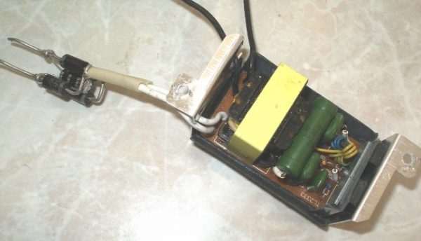
Ready-made charging based on switching power supply
What is required:
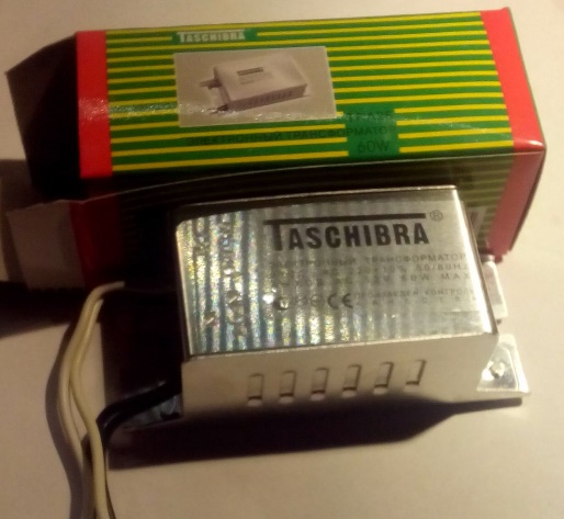
- The transformer is an electronic type from the Chinese manufacturer Tashibra.
- Dinistor KN102. A foreign dinistor is marked DB3.
- Power keys MJE13007 in the amount of two pieces.
- Diodes KD213 in the amount of four pieces.
- A resistor with a resistance of at least 10 ohms and a power of 10 watts. When a resistor of lower power is installed, it will constantly warm up and very soon will fail.
- Any feedback transformer that may be located in older radios.
You can place the circuit on any old board or buy a plate of inexpensive dielectric material for this. After assembling the circuit, it will need to be hidden in a metal case, which can be made from simple tin. The circuit must be isolated from the housing.
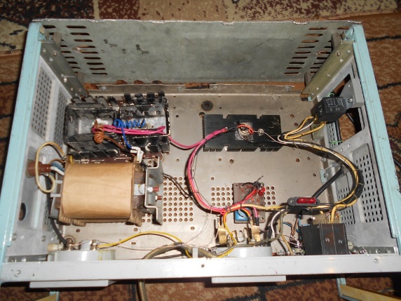
An example of a charger mounted in an old system unit
Do-it-yourself charger sequence:
- Redo the power transformer. To do this, unwind its secondary winding, since Tashibra pulse transformers give only 12 V, which is very small for a car battery. In place of the old winding, 16 turns of a new twin wire should be wound, the cross section of which will not be less than 0.85 mm. The new winding is insulated, and the next one is wound on top of it. Only now it is necessary to make only 3 turns, the wire cross section is not less than 0.7 mm.
- Install short circuit protection. To do this, you need the same 10 ohm resistor. It should be soldered into the gap of the windings of the power transformer and the feedback transformer.
Resistor as short circuit protection
- Using four KD213 diodes, solder the rectifier. The diode bridge is simple, it can work with high-frequency current, and its manufacture occurs according to the standard scheme.
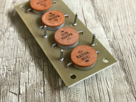
Diode bridge based on KD213A
- We make a PWM controller. It is necessary in the charger, as it controls all the power switches in the circuit. It can be done independently using a field effect transistor (for example, IRFZ44) and reverse conductivity transistors. For these purposes, elements of the KT3102 type are ideally suited.

PWM = high quality controller
- Dock the main circuit with a power transformer and a PWM controller. After that, the resulting assembly can be fixed in a self-made case.
This charger is quite simple, does not require large expenses during assembly, has a small weight. But circuits made on the basis of pulse transformers can not be classified as reliable. Even the simplest standard power transformer will produce more stable performance than switching devices.
When working with any charger, remember that polarity reversal must not be allowed. This charge is protected from the like, but the reversed terminals shorten the battery life, and the variable type resistor in the circuit allows you to control the charge current.
DIY do-it-yourself charger
To make this charge, you will need elements that can be found in an old-style used TV. Before installing them in a new circuit, the details must be checked with a multimeter.
The main part of the circuit is a power transformer, which can not be found everywhere. Its marking: TS-180-2. A transformer of this type has 2 windings, the voltage of which is 6.4 and 4.7 V. In order to get the necessary potential difference, these windings should be connected in series - the output of the first is connected to the input of the second by soldering or an ordinary terminal block.
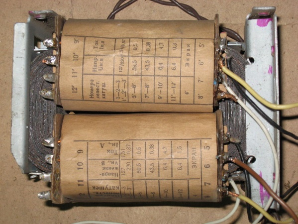
Transformer type TS-180-2
Also, diodes of the type D242A in the amount of four pieces will be needed. Since these elements will be assembled into a bridge circuit, excess heat will be removed from them during operation.Therefore, it is also necessary to find or purchase 4 cooling radiators for radio components with an area of at least 25 mm2.
Only the base remains, for which you can take a plate of fiberglass and 2 fuses, at 0.5 and 10A. Conductors are allowed to use any section, only the input cable should be at least 2.5 mm2.
Charger assembly sequence:
- The first element in the circuit is to assemble a diode bridge. It is assembled according to the standard scheme. The places of conclusions should be lowered down, and all diodes should be placed on cooling radiators.
- From the transformer, from leads 10 and 10 ′, conduct 2 wires to the input of the diode bridge. Now, the primary windings of the transformers should be slightly modified, and for this, a jumper must be soldered between terminals 1 and 1 ′.
- Solder the input wires to terminals 2 and 2 ′. The input wire can be made from any cable, for example, from old electric kettle or any old appliance. If only a wire is available, then a plug must be connected to it.
- A fuse rated at 0.5A should be installed in the gap of the wire going to the transformer. In the gap of the positive, which will go directly to the battery terminal - 10A fuse.
- The negative wire coming from the diode bridge is soldered sequentially to an ordinary lamp, designed for 12 V, with a power of not more than 60 watts. This will help not only to control the charging of the battery, but also to limit the charging current.
All elements of this charger can be placed in a tin case, also made by hand. Fix the fiberglass plate with bolts, and mount the transformer directly on the housing, after placing the same fiberglass plate between it and the tin.
Ignoring the laws of electrical engineering can lead to the fact that the charger will constantly fail. Therefore, it is worth planning the charging power in advance, depending on which to assemble the circuit. If the circuit power is exceeded, then the battery will not be properly charged if there is no excess of the operating voltage.